In 2021 the ROS™ 2 version of MoveIt acquired a novel motion planning architecture. With “Hybrid Planning” finally merged in December, it’s now possible to implement a whole new family of robot applications that require dynamic adaption or updates during trajectory execution. While the architecture is very versatile, the existing default implementations only give a glimpse on what Hybrid Planning is supposed to do in the future. For developers it was still lacking practical examples and design guidelines.
In order to fill this gap, PickNik and Fraunhofer IPA have been working on realizing an industrial robotic welding application using Hybrid Planning. The goal was to streamline the multi-step motion planning approach in an adaptive single-shot execution. This post gives some insights into the design and implementation of the pipeline, as well as our learnings along the way.
Original Welding Pipeline
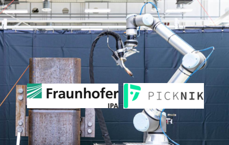
Fraunhofer’s welding robot is a UR10e mounted on a table with a welding gun and a laser scanner attached to the wrist. In the original ROS 1 pipeline, the workpiece is being positioned on the table and has a predefined welding seam that guides the toolpath trajectory. The main difficulty is that the object’s pose is not known with enough accuracy that the very fine tip of the welding gun could be applied in a safe and steady manner. In order to allow for very accurate and robust results, the welding task of the ROS 1 implementation is split into two phases:
1.Scanning Motion:
Trace the predefined welding seam with a laser scanner and generate accurate path waypoints
2.Welding Motion:
Follow scanned waypoints with the tip of the welding gun at constant velocity
Before jumping into our Hybrid Planning adaptation, let’s take a quick look at these motion phases.
Both phases produce very similar motion plans, only that the scanning motion follows the pre-defined welding seam from a safe distance while pointing the scanner at the seam profile. The images below show the robot during the scanning phase next to a visualization of the scanned sensor data, representing the seam profile
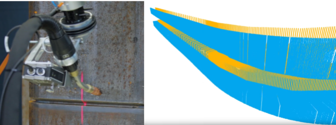
After scanning is completed, the sensor data is processed by iteratively generating Cartesian waypoints and computing a continuous trajectory for the welding gun tip. Below you see the tip being applied at the welding seam which doesn’t allow for large error margins. Additionally, in order to produce consistent welding results as depicted on the right, it’s absolutely critical that the motion velocity is very stable. This also feeds into the design requirements for the Hybrid Planning setup.

Hybrid Planning Approach
The goal of the Hybrid Planning pipeline was to streamline the welding task by combining the two phases of the original setup into a single run. For that, the scanning task would have to be modified so that it could be run online while already applying the welding gun. The general design requirements of the global and local planners come quite naturally when separating static and dynamic constraints of the task:
| Global Planner |
|
| Local Planner |
|
The listed planner requirements don’t cover all of the problems that need to be solved for the whole application. For instance, approaching the seam in a safe way, running the first bits of the welding path where sensor input might be missing and good error handling would involve more sophisticated requirements that are not considered here.
Runtime Logic
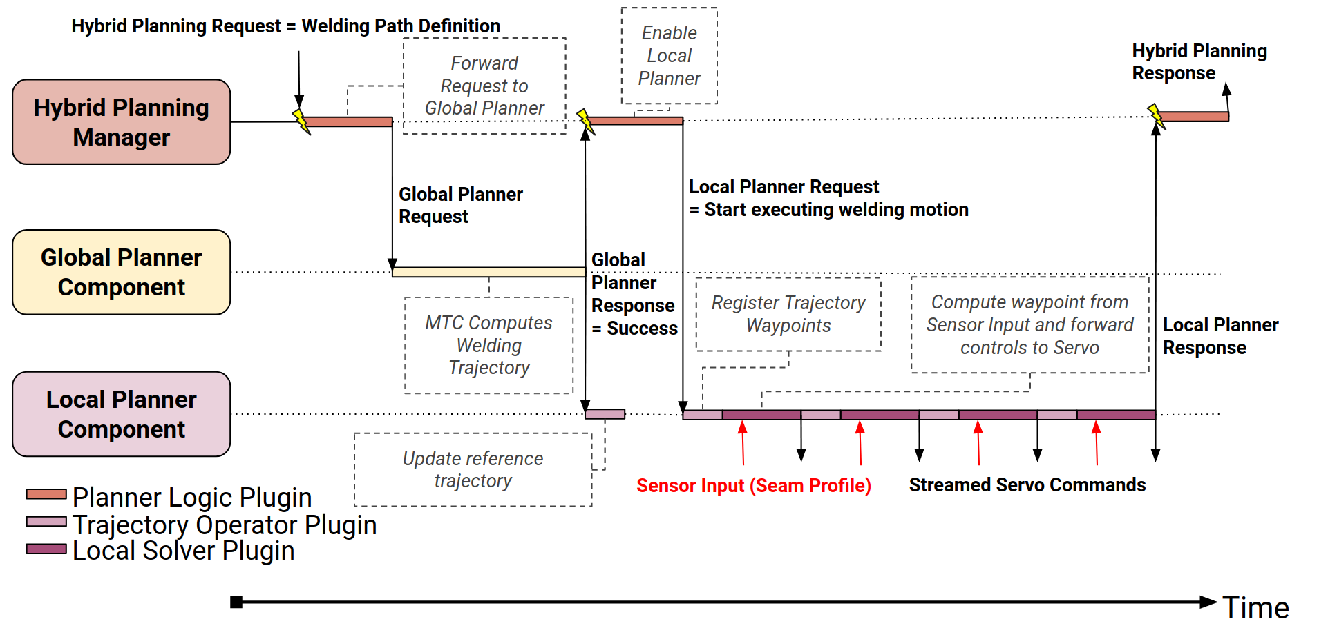
With the planner requirements specified, we draft a minimal runtime logic that defines the sequence of communication and work that the planners should run. The logic shows how first the global planner is requested to produce a global welding trajectory, which is then forwarded to the local planner. The local planner is then enabled for trajectory execution, which effectively almost resembles a closed-loop control pattern: 1. read sensor input, 2. compute waypoint, 3. publish a new control command. When the trajectory has been completed, the local planner terminates and returns the successful action result. There aren’t a lot of implementation details included here, but the drawing should already give an idea on how the pipeline is supposed to work in practice.
Demo Implementation
The setup and source code of the demo can be found in the repo UR10e_welding_demo. It includes the ported launch and configuration packages for bringing up the UR10e robot, both for simulation and hardware runtime. The hybrid_planning_demo package includes the planner implementation, in particular the main node executable which initializes the planning requests and the implementations for the global and local planner plugin interfaces.
The solver of the global planner is implemented by the class GlobalMTCPlannerComponent which, as the name indicates, handles the planning requests with a custom MoveIt Task Constructor (MTC) task implementation. At the time of writing this blog post, the MTC task merely contains a couple stages that handle Cartesian trajectories for approaching, welding, and retreating from the workpiece, as well as a simple trajectory processing step. This task implementation will be replaced with a modified version of the original MTC task from the ROS 1 pipeline once the port of the corresponding library is completed. For now, this task fully serves as a test case for the global trajectory execution which allows us to focus more on the local planner.
The local planner includes two plugin implementations, namely the SimpleServoSampler for the TrajectoryOperatorInterface and the ServoSolver for the LocalConstraintSolverInterface. Which seems complicated at first but makes more sense when looking at the purpose of these plugins. The SimpleServoSampler is the trajectory operator that handles the registration and unwinding of the global reference trajectory. The plugin basically provides the immediately upcoming reference waypoints - or local trajectory - that are supposed to be followed. The ServoSolver plugin, implementing the LocalConstraintSolverInterface, uses iterative local trajectories as target and computes the commands to follow them based on the current robot state. Additionally, the plugin has a subscriber to a TwistStamped message topic that resembles the corrective motion commands that are expected for sensor-based adaptations. In the demo, the twist message can be published using keyboard inputs which will result in modified end-effector rotations. This example shows how the hybrid planning pipeline supports reacting to sensor input while still following the constraints of a global trajectory.
Learnings and Tips
The Hybrid Planning pipeline uses a completely new architecture that requires a lot of thinking ahead and planning in order to produce the desired results. Discussing, simplifying and designing the requirements for the different plugins before starting any of the implementation helps a lot with this. Also, drawing of the runtime logic acts as a mental model that aids with understanding the behavior of the system. We decided to at first start with a very minimalistic implementation that just runs a simple trajectory before iteratively adding more features and improvements. The architecture makes it easy to focus on changing one thing at a time, and that’s probably a best practice that everyone should follow when working with it.
As of now, there is only a very simple set of plugin implementations provided with the hybrid planning package, but as seen here, it often makes a lot of sense to implement custom solvers. The MTC task that we use in the demo is probably not very useful for other settings, just like a sensor-based waypoint adaptation class is probably very specific to its application and context. Because of that it won’t be very easy to provide a feature-rich set of generic hybrid planning solvers that everyone can use for their application just like that. More likely we would continue to build and publish more reference implementations and examples that can be taken as recipes for solving certain types of problems. We hope that at some point there will be a recipe for any class of dynamic motion planning problems where developers can start from instead of building the pipeline from scratch. We are still investigating use cases and have active projects around shaping the ideas and best practices around hybrid planning. Do you have any applications where hybrid planning might be the right approach for you? Or are you already using it in some way and would like to share your questions or learnings? Please reach out to us, we would be happy to receive your feedback.
MoveIt Pro is PickNik Robotics’ commercial robotics software platform that extends the capabilities of the open-source MoveIt project. Designed for unstructured environments, MoveIt Pro provides powerful tools for motion planning, grasping, perception, and behavior sequencing. With pre-built robot behaviors and a modular runtime architecture, MoveIt Pro significantly reduces engineering effort and time-to-deployment. Its hardware-agnostic design supports a wide range of commercial and custom robotic arms, making it ideal for scalable automation across space, manufacturing, and logistics sectors.


