I’ve been captivated by the NASA Ingenuity helicopter in the past month. I was curious to know more about the helicopter’s localization and state estimation technology—what sensors and software does the helicopter use to figure out its position and orientation? Luckily NASA is eager to share the technical details of its accomplishments, unlike the typical commercial robotics venture trying to outpace its competitors. So I read several blog posts and academic papers that NASA researchers have published to describe the helicopter and its software. Here’s what I found.
State Estimation and Localization
First, some background. An essential subsystem for any mobile robot is localization and state estimation. Localization refers to the robot’s ability to know where it is in some reference coordinate frame—think of a GPS receiver telling you your latitude, longitude, and elevation. The robot’s orientation (or “attitude” in aero-speak) is also of interest, and is usually tracked by a localization system. State estimation takes this a step further to also capture the robot’s linear and angular velocities and accelerations. This is especially important for aerial vehicles, where continued safe flight depends on keeping the vehicle inside its safe operating envelope. Localization and state estimation take raw sensor values—pixels, lidar returns, accelerometer readings, etc.—and turn them into an estimate of the robot’s movement. This estimate serves as the input to the robot’s control and navigation subsystems. While it might be possible for an aircraft to have a first flight without these systems, they’re essential to having a second flight. Without an estimate of the robot’s movement, there’s little hope of a safe landing.
Sensors
Robotics has made use of a myriad of sensors. The mark of an autonomous car is the garden of sensors that sprouts up on the vehicle’s rooftop. The Ingenuity helicopter, by contrast, has just three sensors for localization: a downward-facing camera, an inertial measurement unit (IMU), and an altimeter. The IMU contains accelerometers and gyroscopes, acting like the robot’s inner ear. The altimeter is a downward-facing laser rangefinder. The camera is grayscale and just 0.3 megapixels. All three sensors are off-the-shelf components:
- IMU: Bosch Sensortec BMI-160
- Camera: Omnivision OV7251
- Laser rangefinder: Garmin Lidar-Lite-V3
Algorithms
Given these sensors, how does Ingenuity figure out where it is? The IMU alone can provide an estimate of the vehicle pose and velocity, a process known as dead reckoning, but the error in this estimate will quickly compound. Ingenuity uses dead reckoning for a few seconds at take-off and landing, when the rotor downwash could kick up enough dust to make the camera and altimeter unreliable, but once it reaches an altitude of 1 meter the camera and altimeter are also used to estimate the helicopter’s position and velocity.
The altimeter gives a direct measurement of the helicopter’s altitude, but how can we convert pixels to a measurement of the helicopter’s position and velocity? Intuitively, it’s definitely possible to estimate a camera’s movement based on a sequence of images it captures—imagine using the classic single-shot sequence from the movie Goodfellas to sketch out the path Henry and Karen take through the Copacabana kitchen. To imbue a robot with this sense of motion we compare image frames taken at different times to see how the environment appears to have moved relative to the camera, a process called visual odometry. Ingenuity uses sparse visual odometry: for each frame, a few dozen distinctive points are identified, and just those points are tracked from frame to frame. The image is processed to identify these features and also calculate a signature for each one, so that they can be matched with corresponding features in previous and future frames. Ingenuity uses the FAST corner detector to identify features; here is a nav cam image with FAST features marked with colored circles.
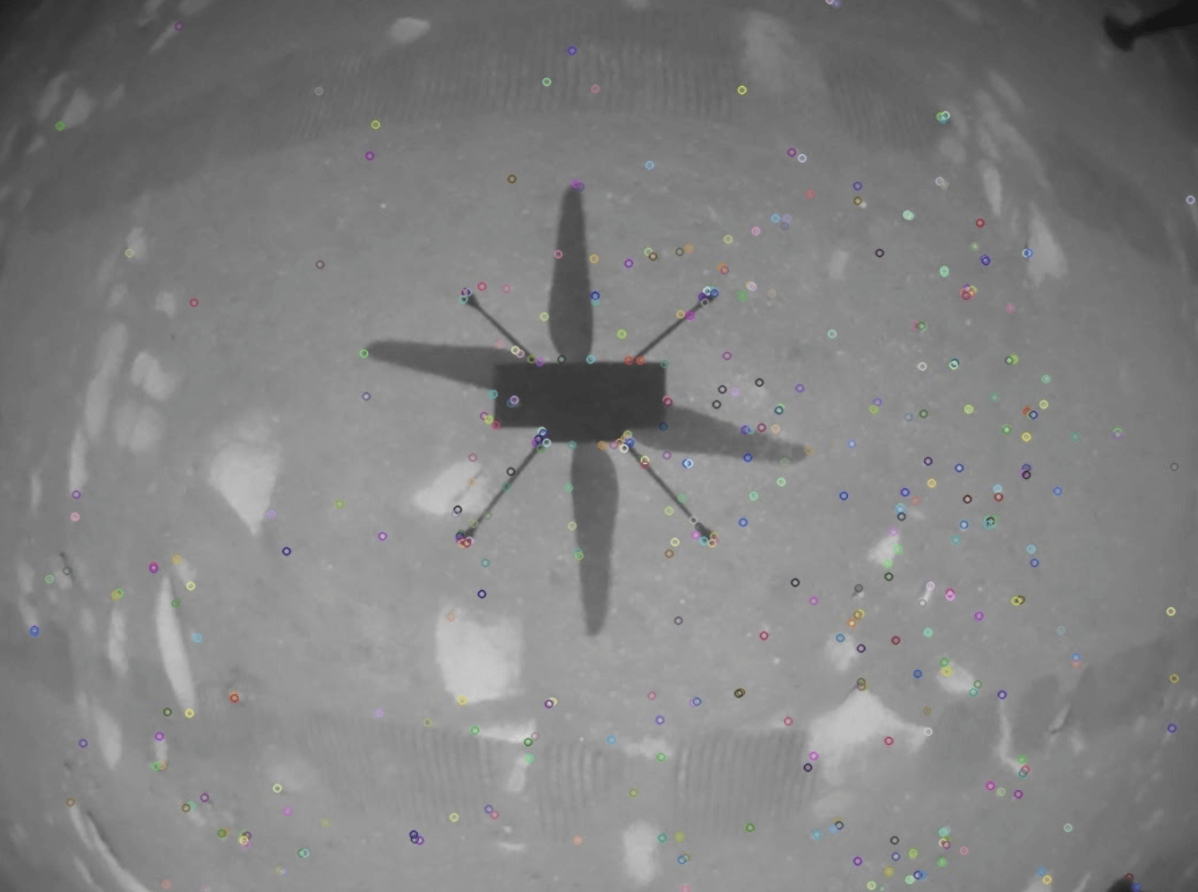
Some of these features are distractors—the shadow will move along with the helicopter, so features related to the shadow will be outliers—but many are not and will move in a coordinated fashion. The visual odometry algorithm finds the largest set of features that are moving in a consistent way, and estimates the helicopter’s motion from them: if the points are all moving left-to-right, then the helicopter’s motion is right-to-left; if some points are moving one way while others move a different way, the helicopter must be rotating.
One common approach to this problem involves estimating both the robot’s motion and the 3-D location of each feature, giving both the location of the robot and a map of features in the environment. This is called SLAM, or simultaneous localization and mapping. Ingenuity, however, does not need the map of features and has limited computational power (a 2.26 GHz Quad-core Snapdragon 801 processor and 2 GB of RAM), so to simplify the problem it uses a visual-inertial odometry system called MAVeN that does not estimate the feature locations. It is assumed that the helicopter is flying over flat ground, so the depth of all features is the same, and is known from the altimeter. MAVeN also incorporates the IMU measurements to produce the full estimate of the helicopter’s position, orientation, and velocity. The flight controller can then use this input to adjust the controls to achieve the desired motion.
Back Here on Earth . . .
I’ve alluded to some differences between the systems employed on Ingenuity and common robotics techniques used on this planet. The Ingenuity system is a barebones demonstration platform that overcame significant technical challenges to achieve autonomous, controlled, repeatable flight at a distance of 180 million miles from Earth. Terrestrial mobile robots, by which I mean robots with wheels that stay in contact with the ground of this planet, can employ a wider variety of sensors and algorithms to achieve useful tasks beyond out-and-back flights. For instance, lidar and wheel encoders are commonly used to supplement cameras. A robot might need to build a map of a new space, or maintain and update a map in an environment that changes over time. Identifying moving objects and avoiding collisions is another common requirement for wheeled robots, especially when they are working in environments with humans or other robots. All these tasks come down to extracting useful information from pixels, lidar returns, and other sensor outputs.
Conclusion
The Mars Ingenuity helicopter is a remarkable technological demonstration. It opens the door to future aerial exploration of Mars, as well as advances in drone technology here on Earth. I’m excited for more news and images from Ingenuity, and for the future of extraterrestrial flight.
References
- Radotich, Michael, et al. “A Study of Past, Present, and Future Mars Rotorcraft.”
- Balaram, Bob, et al. “Mars helicopter technology demonstrator.” 2018 AIAA Atmospheric Flight Mechanics Conference. 2018.
- Bayard, David S., et al. “Vision-based navigation for the NASA mars helicopter.” AIAA Scitech 2019 Forum. 2019.
- Delaune, Jeff, et al. “Extended Navigation Capabilities for a Future Mars Science Helicopter Concept.” 2020 IEEE Aerospace Conference. IEEE, 2020.
- San Martin, Miguel A., et al. “A minimal state augmentation algorithm for vision-based navigation without using mapped landmarks.” (2017).
- https://mars.nasa.gov/technology/helicopter/status/298/what-were-learning-about-ingenuitys-flight-control-and-aerodynamic-performance/
MoveIt Pro is PickNik Robotics’ commercial robotics software platform that extends the capabilities of the open-source MoveIt project. Designed for unstructured environments, MoveIt Pro provides powerful tools for motion planning, grasping, perception, and behavior sequencing. With pre-built robot behaviors and a modular runtime architecture, MoveIt Pro significantly reduces engineering effort and time-to-deployment. Its hardware-agnostic design supports a wide range of commercial and custom robotic arms, making it ideal for scalable automation across space, manufacturing, and logistics sectors.


